Joystick Overview
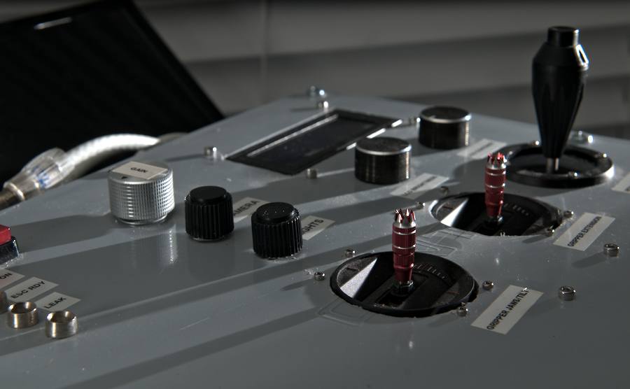
The joystick used for this project is of the analog two axis type with a push button switch on the top of the handle. You may or may not be familiar with how an analog joysticks work, but the simple explanation is as follows: each of the two axes of movement (x and y we will call them) are connected to two separate potentiometers. As the two potentiometers are rotated during movement of the joystick, a voltage reading from zero to VSS of the circuit is output onto the wiper of the potentiometer (lets use "pot" as short for potentiometer). The voltage reading of the wiper can then be fed into an analog input of our microcontroller and converted to a digital value with which we can do all sorts of things. In our case, we will perform a series of steps to convert these analog values into 8 bit numbers which will be sent to the ESCs and control boards of our ROV. There they will be used to control the speed and direction of the six brushless DC motors as well as the onboard camera, lights and gripper arm.
ADC
Since I have already explained the use and configuration of the PIC16F1937's ADC module in an earlier tutorial, I won't spend much time going over that here. However, I will talk about the differences in implementation of the ADC module for our "ROV-specific" needs. Seven analog inputs are used in the control box MCU, with each input connected to a potentiometer wiper found in the various joysticks and control knobs. You will see how the program continuously reconfigures the ADC module to change which input is used as the basis of an AD conversion. This allows us to perform seven separate AD conversions and then come up with digital values to be sent to the ROV.
The depth (direction of travel along the z-axis) and rotation (rotational movement about the z-axis) of the ROV are controlled in the exact same manner with the exception of the process being interrupt driven. Depressing the push-button switch in the handle of the joystick triggers an interrupt which samples the analog inputs in the same manner as described above but with positive y-axis movement of the joystick translated to positive z-axis direction of travel for the ROV (movement towards the surface) and negative y-axis joystick movement translated as negative z-axis direction of travel for the ROV. Additionally, the interrupt translates positive x-axis movement of the joystick as a clockwise rotation about the z-axis and a negative x-axis joystick movement is translated as a counter-clockwise rotation about the z-axis for the ROV. I implemented a series of flags and an encoding scheme to keep track of the intended directional "state" of the ROV based on joystick movement.
Serial Communication
The control box uses a series of "handshakes" to send the following nine data packets to the ROV via the RS-232 transceivers. The designation of the four packets is as follows:
- "State" = Intended overall direction of ROV
- "Forward Speed" = Required speed for motors spinning in forward direction
- "Reverse Speed" = Required speed for motors spinning in reverse direction
- "Up/Down Speed" = Required speed for the two horizontally mounted thrusters
- "Camera Servo" = Position of the camera servo
- "LED Lights" = Brightness value for on-board LED lights
- "Lead Screw" = Speed and direction of motor that drives the gripper arm lead screw
- "Gripper tilt" = Used to tilt the gripper jaws up and down
- "Gripper Jaws" = Used to open/close the gripper jaws
The MCU program running the ROV utilizes a counter and handshake procedure to keep track of the packets and control the flow of data. The control box also utilizes two commands to retrieve infomation from the ROV regarding the temperature sensor and battery monitor. In a later section of this tutorial we will cover the implementation of the PIC's UART module that is interfaced with the RS-232 transceivers.