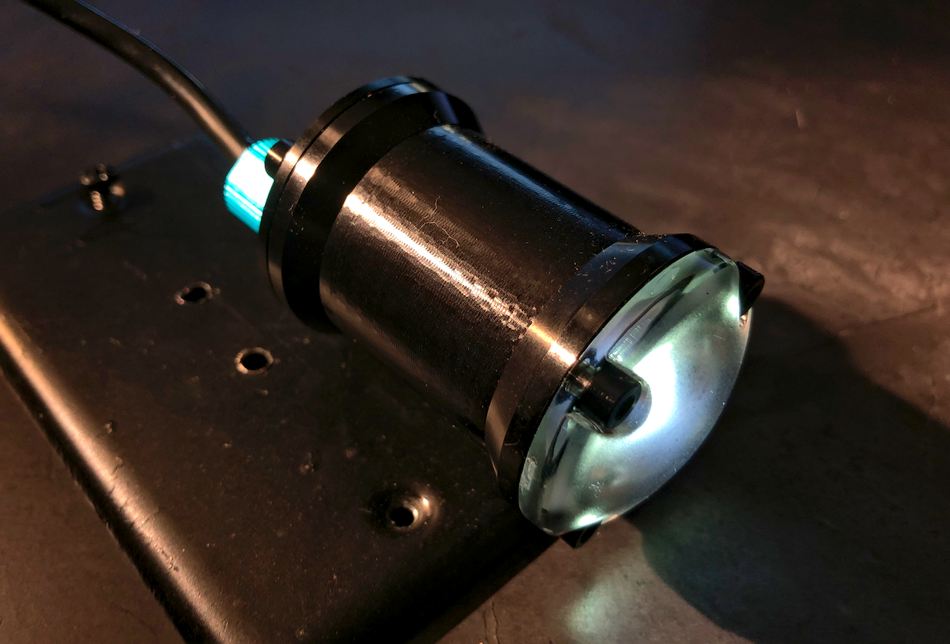
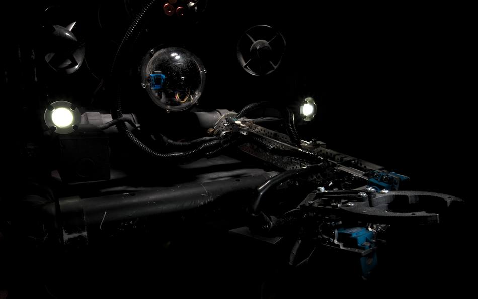
The first test dives undertaken by this ROV were in relatively shallow/clear water where the sunlight was strong enough to require little need for external lighting. Once deeper dives were attempted it become apparent that some form of on-board lighting was going to be necessary (if I wanted to see anything through the camera). I decided to try out the Blue Robotics Lumen Subsea Light (version #2) . This light is rated to a depth of 500m and can be controlled in a simple "on/off" fashion as well as dimmable control via PWM signals. (Our focus will be on dimmable control.) Specifically, we will design a circuit to receive values via the i2c protocol from the main MCU of the ROV (which of course receives signals from the control box). The reason for using a separate circuit board and the i2c protocol is the fact that the main ROV MCU (which is a Microchip PIC16F1937 ) has a limited number of PWM outputs and they are already being used for other tasks relating to ROV and camera control. We will address the following three parts of the system as they pertain to controlling the LEDs:
- Control Box (potentiometer adjustment)
- ROV (i2c communication with LED controller)
- LED Controller (i2c communication and PWM control)
Control Box (potentiometer control/adjustment)
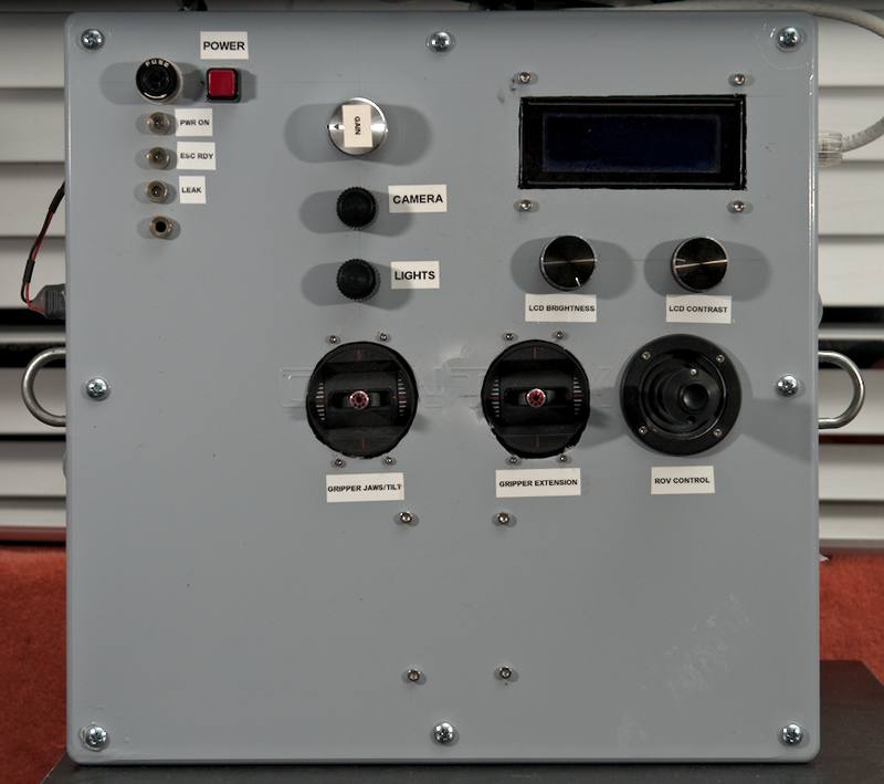
The ROV lights are dimmable-controlled via a 1 kOhm potentiometer mounted on the control panel:
In a similar manner to the joystick and camera-tilt potentiometers, we perform an ADC inside the main loop of main.asm
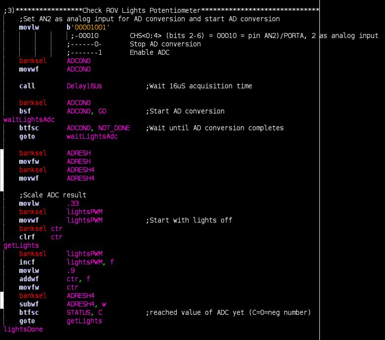
In a similiar manner to the camera-tilt potentiometer, we set the correct analog input pin, obtain the corresponding ADC result and then scale it to suit our purposes. While we haven't yet discussed the code found in the LED-controller circuit, know that the LEDs are controlled with PWM signals having pulse widths from 1.1mS to 1.9mS which correspond from "off" to "fully on" respectively (all values inside this range corresponding to dimmed values). In order to be of use to the PWM module of the LED-controller (not yet discussed) we need to scale the ADC results to a range of values from 34 to 60. These scaled values eventually make their way to the PWM5DCH register of the PIC16F18313 microcontroller found in the LED-controller circuit.
- ADC value range: 0-255
- Scaled range for PWM: 34-60
These scaled values are held in the variable "lightsPWM" and sent to the ROV (via UART) at the end of the "sendThrust" routine (found in the uart.asm file).
ROV (i2c communication to LED controller)
Upon receiving this LED value from the control box, the ROV saves it in a variable also named "lightsPWM". Once inside the main-loop, the program determines if we are ready to process and send all of the received UART packets to their respective destinations (motor ESCs, camera servo and LED controller) by way of checking "readyThrust" bit #1. The program then initiates I2C communication with the LED-controller. This code is shown below and can be found in the main.asm file of the ROV program.
Notice that the program first checks that the value is within the acceptable range for the LEDs just in case a UART transmission sends the packets out of order. An i2c "START" condition is executed along with the i2c bus address for the controller (b'00001110'). The "lightsPWM" variable is then clocked out on the i2c lines.
LED Controller (i2c communication and PWM control)
The microcontroller used for the LED controller circuit is a Microchip PIC16F18313 . The circuit schematic for the LED controller is shown below:
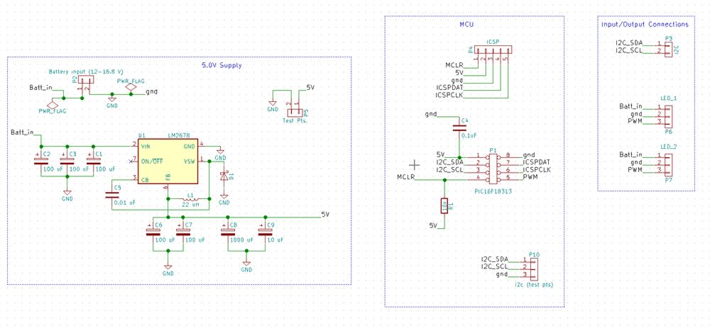
(A high-res version of the schematic can be found here )
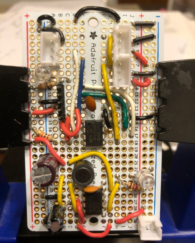
After some bread-board prototyping, the circuit was constructed with proto-board (shown below) with the intention of having a PCB made in the future. I used JST-XH headers for all external connections to the board (power, i2c and LED connections). This first prototype used an undersized 1A switching regulator.
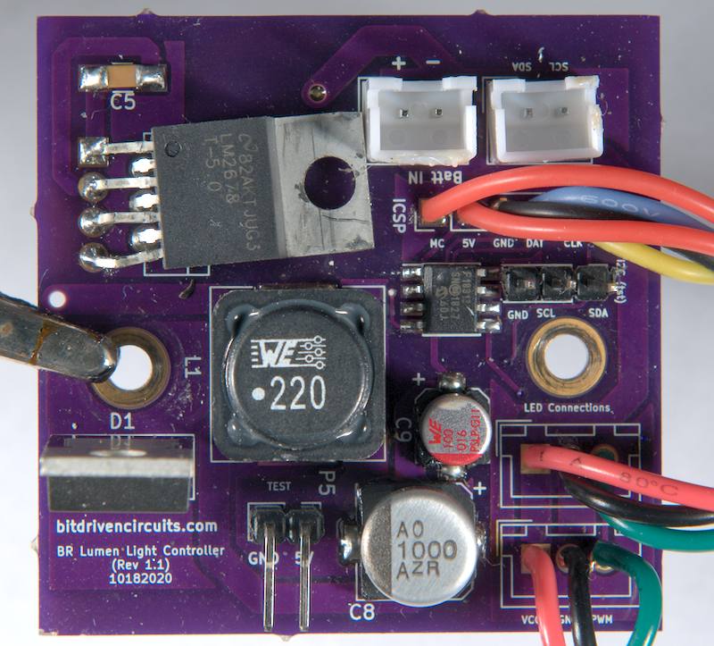
Afterwards, I designed a PCB using kicad and had it fabricated by Oshpark.
Front side of PCB (with larger 5A switching regulator for potential future addition of more LED lights):
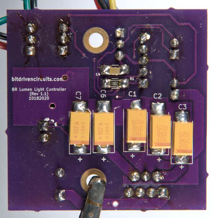
Back side of PCB (pardon the flux residue):
On a side note, the Blue Robotics Lumen lights are advertised as being able to be "daisy-chained" by dissembling them and connecting the wires together. This would allow for a single cable from the waterproof housing to control multiple lights as opposed to a cable for each individual light. I did try this method but had an insanely difficult time taking the lights apart (resulting in one unit being destroyed). This seems due to intense suction/vacuum fighting against you while attempting to pull the end cap off. Despite opening/removing every possible air-path in an attempt to reduce the vacumm effect, the amount of force required for separation (bench vise, channel locks and significant arm strength) was too great to preserve the "integrity' of the components. For this reason I have decided against such an approach and run separate penetrators/cables from the water-tight housing for each individual light. Your mileage may vary but it's something to be aware of.
LED-controller code
Inside the initialization section of the program file (named lightControllerMain.asm ), the I2C module is configured in slave-mode to trigger an interrupt upon a receiving a "START" condition. The PWM module is also configured to provide a frequency of about 500 Hz and an initial pulse width of 1.1 mS via a default value of "34" in the PWM5DCH register. The following min/max values of PWM5DCH correspond to the following PWM pulse widths:
- When PWM5DCH = 34, Pulse-width = 1.1 mS
- When PWM5DCH = 60, Pulse-width = 1.9 mS
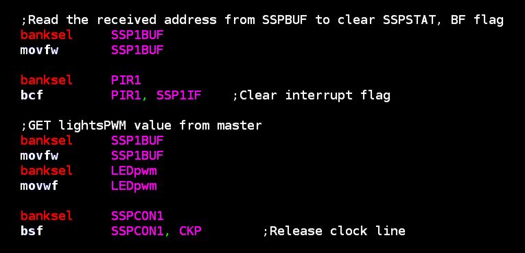
Inside the Interrupt Service Routine (ISR), the 8-bit i2c packet is received from the master device (the ROV) and saved in the variable named "LEDpwm":
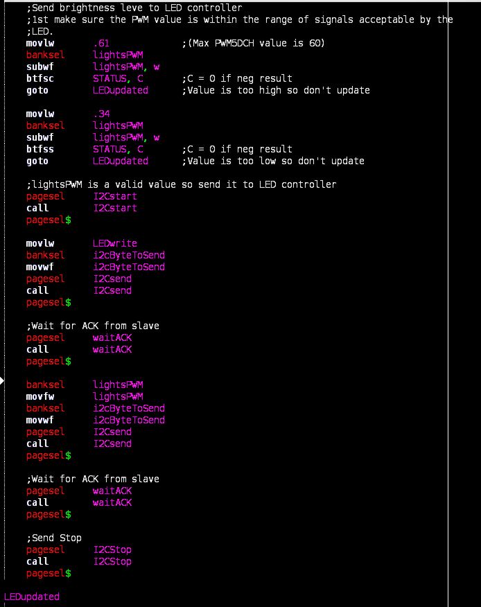
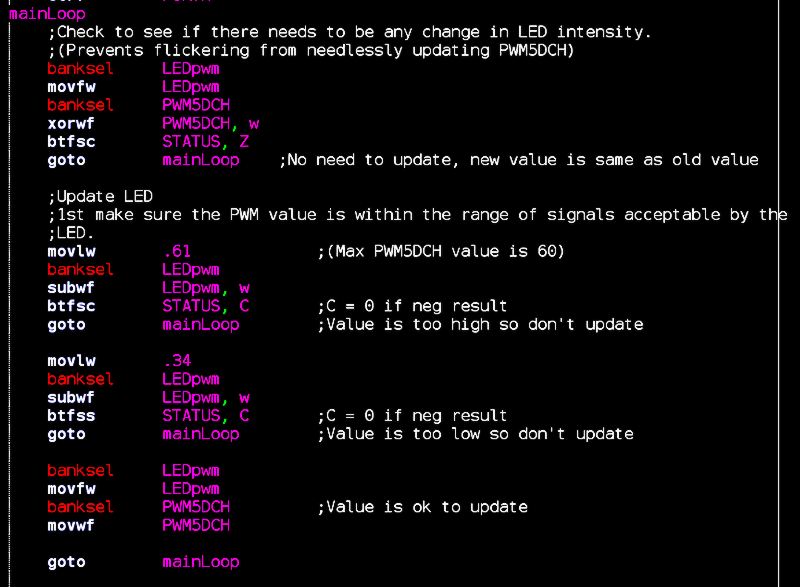
After the program exits the ISR, it returns to the main-loop. In most cases, there won't be any required changed in LED intensity and the received values will be the same as the old values. In order to prevent the needless updating of the PWM module, the main-loop checks for this scenario and skips the updating until it receives a value that is different. Once this happens, PWM5DCH is updated with this new number. The code also double checks to make sure the PWM values are valid for the LED lights. The screenshot below show this code inside the main-loop:
This concludes our discussion of the ROV lighting. As was mentioned towards the top of this page, you can also wire these LEDs to be controlled in a simple on/off fashion. This is accomplished by simply feeding the positive voltage supply of your circuit to the yelow signal wire of the LED to turn it on and grounding this same wire to turn it off.
Continue on to ROV (part 6/gripper arm hardware)...